Introduction: Why Understanding DICOM Image Rendering Matters
Every day, thousands of medical imaging devices around the world generate DICOM files containing X-rays, CT scans, MRI sequences, ultrasound studies, and nuclear medicine acquisitions. These files are more than ordinary images — they embed raw pixel data alongside rich clinical metadata that determines how those pixels should be displayed. Unlike a JPEG or PNG file that is ready to render as-is, a DICOM image requires interpretation: the rendering software must read the pixel data, apply mathematical transformations based on metadata tags, and produce a visually meaningful image on screen.
For healthcare IT professionals, clinical engineers, researchers, and students, understanding how this rendering pipeline works is essential. It explains why the same DICOM file can look different on two viewers, why windowing matters for diagnosis, and how browser-based tools can now handle tasks that once required dedicated PACS workstations. This article walks through the complete rendering pipeline, from raw pixel bytes to the final image you see on screen. You can follow along by opening any DICOM file in our online DICOM Image Viewer.
DICOM Pixel Data: The Raw Material
At the heart of every DICOM image is the Pixel Data tag (7FE0,0010). This tag contains the actual image values — a contiguous block of bytes representing pixel intensities arranged row by row, from top-left to bottom-right. The format of these bytes is defined by several companion tags that the renderer must read before it can interpret the data.
The Rows tag (0028,0010) and Columns tag (0028,0011) define the image dimensions. Bits Allocated (0028,0100) specifies how many bits are reserved per pixel sample — typically 8 or 16. Bits Stored (0028,0101) indicates how many of those bits actually carry data (for example, a 12-bit image stores values 0–4095 within a 16-bit container). Pixel Representation (0028,0103) tells the renderer whether values are unsigned (0) or two’s complement signed (1).
For color images, the Samples Per Pixel tag (0028,0002) is set to 3 (one sample each for red, green, and blue), while grayscale images have a value of 1. The Planar Configuration tag (0028,0006) specifies whether color samples are interleaved (R1G1B1R2G2B2…) or stored in separate planes (R1R2…G1G2…B1B2…).
Together, these tags form a complete recipe that allows any standards-compliant viewer to decode the raw bytes into a meaningful pixel array. Without them, the Pixel Data tag is just an opaque blob of binary data.
Photometric Interpretation: How to Read the Pixels
The Photometric Interpretation tag (0028,0004) is one of the most important rendering parameters. It tells the viewer what the pixel values represent and how to map them to display colors.
MONOCHROME2 is by far the most common interpretation in modern radiology. Higher pixel values correspond to brighter (whiter) display pixels. A CT scan where air appears black and bone appears white uses MONOCHROME2. Most CT, MRI, DR, and DX images use this interpretation.
MONOCHROME1 is the inverse: higher pixel values appear darker. This convention dates back to the original film-based radiology workflow, where higher optical density (darker film) corresponded to higher exposure values. Some older computed radiography (CR) systems and digitized film scanners produce MONOCHROME1 images. A correct renderer must invert the grayscale mapping for these images, or they will appear as negatives.
RGB images store three color channels per pixel. Dermatology photographs, pathology whole-slide images (when stored as DICOM), visible-light endoscopy, and ophthalmology fundus photos typically use RGB photometric interpretation. No windowing is applied to RGB images — the values map directly to display colors.
Other less common interpretations include YBR_FULL and YBR_FULL_422 (luminance-chrominance color models used with JPEG compression), PALETTE COLOR (indexed color with lookup tables), and YBR_ICT / YBR_RCT (used with JPEG 2000). A robust viewer should handle at least MONOCHROME1, MONOCHROME2, and RGB, which together cover the vast majority of clinical images.
Windowing: The Key to Clinical Image Interpretation
A 12-bit CT image can contain pixel values ranging from -1024 (air) to +3071 (dense bone or metal) — a total of 4,096 distinct gray levels. A standard computer display, however, can only show 256 gray levels (8 bits per channel). Displaying all 4,096 levels at once would compress the visible contrast so much that subtle tissue differences become invisible to the human eye.
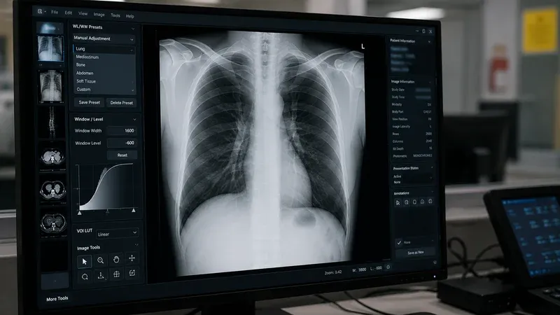
Windowing (also called window/level or contrast/brightness) solves this problem by selecting a narrow range of pixel values and stretching it to fill the display’s 0–255 range. Two parameters define the window:
- Window Center (WC), also called level, specifies the midpoint of the visible range. Pixel values at the center appear as medium gray.
- Window Width (WW) specifies the total width of the visible range. Values below
WC - WW/2appear black; values aboveWC + WW/2appear white.
The mathematical mapping for each pixel is straightforward. Given a raw pixel value v:
- If v ≤ WC − WW/2, the display value is 0 (black).
- If v ≥ WC + WW/2, the display value is 255 (white).
- Otherwise, display = ((v − WC + WW/2) / WW) × 255.
DICOM files often include default window values in the Window Center (0028,1050) and Window Width (0028,1051) tags. Some files contain multiple window presets separated by backslash characters — for example, a CT might provide separate lung, bone, and soft tissue windows. The viewer typically uses the first preset as the default and allows the user to adjust interactively.
Common Clinical Windows
Radiologists use standardized window presets to examine different anatomical structures in CT images:
- Lung window: WC = −600, WW = 1500. Optimized for air-filled structures, bronchi, and pulmonary vasculature.
- Mediastinum / soft tissue: WC = 40, WW = 400. Shows the heart, great vessels, lymph nodes, and muscle.
- Bone window: WC = 300, WW = 1500. Highlights cortical bone, fractures, and calcifications.
- Brain window: WC = 40, WW = 80. Narrow window for detecting subtle density differences in gray and white matter.
- Liver window: WC = 60, WW = 160. Optimized for hepatic parenchyma and lesion detection.
Being able to switch between these windows interactively is one of the most important features of any DICOM viewer, because the same raw data can reveal completely different clinical information depending on the window settings.
Transfer Syntaxes: How Pixel Data Is Encoded
The DICOM Transfer Syntax UID (0002,0010) in the file meta header specifies how the entire file — including pixel data — is encoded. The transfer syntax determines byte order, value representation encoding, and whether pixel data is compressed.
Uncompressed transfer syntaxes store pixel data as raw byte arrays. The three most common are Implicit VR Little Endian (1.2.840.10008.1.2), Explicit VR Little Endian (1.2.840.10008.1.2.1), and Explicit VR Big Endian (1.2.840.10008.1.2.2, retired). With uncompressed data, the renderer can read pixel values directly from the byte array using simple index arithmetic: for a 16-bit image, pixel i starts at byte offset i × 2.
Encapsulated (compressed) transfer syntaxes wrap the pixel data in a sequence of fragments, each containing a compressed image frame. Common compressed syntaxes include JPEG Baseline (1.2.840.10008.1.2.4.50), JPEG Lossless (1.2.840.10008.1.2.4.70), JPEG 2000 Lossless (1.2.840.10008.1.2.4.90), and JPEG 2000 Lossy (1.2.840.10008.1.2.4.91). To render encapsulated data, the viewer must extract the fragment bytes, identify the compression format (typically by examining magic bytes at the start of the frame), and decode using the appropriate codec — often delegated to the browser’s native image decoder.
Understanding transfer syntaxes is critical for troubleshooting “blank” or “corrupt” images. A viewer that does not support the transfer syntax of a particular file will fail to decode the pixel data, even though the rest of the DICOM metadata is perfectly readable.
Multi-Frame Images and Cine Loops
While most DICOM objects contain a single frame (one image), several modality types produce multi-frame objects that store multiple images within a single DICOM file. The Number of Frames tag (0028,0008) indicates how many frames are present.
Common multi-frame modalities include:
- Cardiac cine MRI: 20–30 frames capturing one cardiac cycle.
- Nuclear medicine: Dynamic studies with hundreds of frames over time.
- Enhanced CT and MR: All slices of a volume stored as frames in a single object.
- Ultrasound clips: Short video sequences stored as multi-frame DICOM.
- Digital subtraction angiography (DSA): Fluoroscopic frame sequences for vascular imaging.
For uncompressed multi-frame images, each frame occupies a contiguous block of bytes whose size equals rows × columns × samples_per_pixel × (bits_allocated / 8). The renderer calculates the byte offset for frame n as pixel_data_offset + n × frame_size.
For encapsulated multi-frame images, each fragment in the pixel data sequence typically corresponds to one compressed frame. The renderer must iterate through the fragment list, extract the bytes for the requested frame index, and decode them individually.
A good viewer allows frame-by-frame navigation via a slider or keyboard shortcuts, and optionally supports cine playback at a configurable frame rate for temporal sequences.
Bit Depth and Pixel Representation
The bit depth of a DICOM image determines its dynamic range and has a direct impact on windowing behavior:
- 8-bit images (Bits Allocated = 8): 256 possible values (0–255). Common in ultrasound secondary captures and some older CRs. Windowing has limited effect because the full range already fits a standard display.
- 12-bit images (Bits Allocated = 16, Bits Stored = 12): 4,096 possible values. Standard for CT scanners. Windowing is essential to explore different tissue densities.
- 16-bit images (Bits Allocated = 16, Bits Stored = 16): 65,536 possible values. Used in PET scans and some MR acquisitions. Provides the widest dynamic range and the most flexibility for windowing.
When Pixel Representation is 1 (signed), values above the midpoint of the stored range are interpreted as negative numbers using two’s complement. For a 16-bit signed image, values range from −32,768 to +32,767. CT images in Hounsfield Units are typically signed, with air at approximately −1000 HU and water at 0 HU.
The renderer must correctly handle both signed and unsigned pixel data. A common bug in naive implementations is treating all values as unsigned, which causes signed CT data to wrap around and produce artifacts in the displayed image.
Browser-Based Rendering: How It Works
Modern browser-based DICOM viewers use JavaScript and the HTML5 Canvas API to render medical images without any plugins or desktop software. The rendering pipeline in a browser typically follows these steps:
- File loading: The user selects a DICOM file via a file picker or drag-and-drop. The File API reads the bytes into an ArrayBuffer.
- Parsing: A JavaScript DICOM parser (such as dicom-parser) reads the binary stream, extracting all tags and their values into a structured dataset object.
- Metadata extraction: The renderer reads Rows, Columns, Bits Allocated, Bits Stored, Pixel Representation, Photometric Interpretation, Window Center, and Window Width from the parsed dataset.
- Pixel data access: For uncompressed data, the renderer creates a TypedArray view (Uint8Array or Int16Array) over the pixel data bytes. For encapsulated data, it extracts frame fragment bytes and decodes them via a Blob URL loaded into an Image element.
- Windowing: For grayscale images, each pixel value is mapped to a 0–255 display value using the windowing formula. For MONOCHROME1, the result is inverted.
- Canvas rendering: The computed display values are written into an ImageData object (an RGBA pixel array) and painted onto the canvas via
putImageData().
This entire pipeline runs locally in the browser. No pixel data is transmitted to any server, making it inherently privacy-safe. Performance is excellent for typical clinical images: JavaScript TypedArrays provide near-native memory access speeds, and canvas compositing is hardware-accelerated on most modern devices.
Privacy Advantages of Client-Side Rendering
One of the most significant benefits of browser-based DICOM rendering is data isolation. When a user opens a DICOM file in a client-side viewer, the file contents never leave the device. There is no upload step, no server-side processing, and no temporary storage in a cloud environment. This architectural property provides several important guarantees:
- No risk of accidental PHI exposure through network interception or server breaches.
- No need for Business Associate Agreements (BAAs) with the viewer provider.
- Compatible with air-gapped and restricted network environments.
- Audit-friendly: the data processing trail is entirely within the user’s browser session.
For educational institutions, research labs performing preliminary data review, and clinical engineers testing integration workflows, client-side rendering provides a practical balance between functionality and compliance.
Conclusion
DICOM image rendering is a well-defined pipeline that transforms raw pixel bytes into clinically meaningful visual information. Understanding the roles of photometric interpretation, windowing parameters, transfer syntaxes, bit depth, and multi-frame structure gives you the knowledge to troubleshoot rendering issues, evaluate viewer capabilities, and make informed decisions about imaging workflows. Whether you are a healthcare IT professional maintaining a PACS, a researcher building an AI pipeline, or a student learning medical imaging, mastering these concepts will serve you throughout your career.
Ready to explore? Open any DICOM file in our DICOM Image Viewer and experiment with windowing, frame navigation, and zoom — all without uploading a single byte to the cloud.